Parallel ports.
What is a parallel port?
Parallel ports were originally designed by IBM to connect printers to their IBM PC. They designed the port so that printers made by Centronics could be connected to it.
IBM decided to use a 25 pin D-sub connector. This connector looks like a DB25 serial connector.
Centronics, decided to use their own type of connector and the name for the port later became known as the "centronics port" or connector.
Printer Cable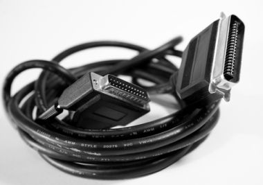
If you look at the above picture you will notice that on the one side there is a 25 pin D-sub or DB25 connector. On the other side there is the centronics connector.
The basics
Parallel interfaces are usually found on personal computers and laptops. It is used to connect devices to your computer.
These ports are also identified as LPT ports in the operating system.
A printer is an example of a parallel device. There are other devices like scanners, cd burners, tape backup devices etc.
When you connect a printer to a parallel connector, data is sent in parallel to the device. It send 8 bits on pins 2-9 in parallel to the device.
If you look at serial communications, bits are sent in serial, one bit at a time, over the cable. So, you can achieve greater throughput on a parallel interface cause it sends 8 bits instead of 1.
Parallel interface on PC (Circled in black)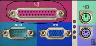
If you look at the devices that you can connect to parallel, it makes sense why IBM designed the parallel interface.
Since USB was developed, people rarely connect their printers to parallel ports. The ease of connecting a printer via USB has made parallel connections almost redundant.
Printer manufacturers also build network interfaces in their printers so, the printer is accessible via the network as a remote printer from the operating system.
How does it work?
Like I said earlier, data is sent in parallel over a parallel interface. This means that you can send about 50 - 100 kilobytes of data on a standard parallel interface.
Lets look at the pin outs of a standard parallel interface.
Parallel pin outs connector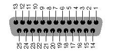
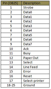
Parallel communications uses a strobe to notify the receiving device that it must count the voltages in it's data lines. The strobe is just a voltage, 2.8-5 volts, that is sent on pin 1.
The receiving device then counts the voltages on the data lines. 2-9, and 8 bits or 1 byte is counted from the data lines.
Pin 10 is for acknowledgment, again just a voltage, to notify the sender that it received the data.
Then there are pins that charges if the printer is out of paper, line feeds and so on. Just have a look at the pin outs.
What other specifications are there?
Besides the normal Standard Parallel Port (SPP), which is bi-directional, you also get Enhanced Parallel Port (EPP) and Extended Capabilities Port (ECP).
The original specification for parallel was unidirectional. This means that data could only be sent in one direction at a time. With the SPP specification data could now be sent both ways on the pins.
EPP was developed to cater for other devices and not just printers. The specification also allowed faster data transmission.
ECP was developed for only printers and faster transfers.
Return from Parallel Ports to Computer Ports
Back to What is My Computer

